Solar Mounting System | Sunlock — TechBulletin ***

Lilian

Corrosion on Solar Racking

INTRODUCTION

The SunLock family of solar PV framing products is designed to have a service life of 25+ years, matching the lifetime of solar modules. This report describes some key points related to corrosion and why a 25+ year service life can be expected. 

FUNDAMENTALS

SunLock rooftop components are fabricated from 6000 series aluminium and 304 stainless steel.

STANDARDS

AS/NZS 5033:2012 discusses corrosion in section 2.2.7, including the following statements: “Module mounting frames…shall be made from corrosion resistant materials suitable for the lifetime and duty of the system…”

“If aluminium is installed in a marine or other highly corrosive environment, it shall be anodized to a thickness and specification suitable for the location and duty of the system.”

“Bolts and nuts should typically be stainless steel.”

“Care shall be taken to prevent electrochemical corrosion between dissimilar metals…Stand-off materials shall be used to reduce electrochemical corrosion between galvanically dissimilar metal surfaces…”

AS/NZS 2312:2002 provide definitions for the corrosive classification of atmospheric environments, as summarised in the table below:

CORROSION ENVIRONMENT DESCRIPTION

CORROSION ENVIRONMENT DESCRIPTION

SUNLOCK RAILS, BRACKETS, CLAMPS AND BOLTS

SunLock is compliant with relevant standards as it is fabricated from 6000 series aluminium and stainless steel 304 fasteners. 

COASTAL ENVIRONMENTS

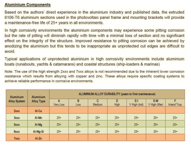
The suitability of mill finish (i.e. non anodised) 6000 series aluminium SunLock components for use in coastal environments has been analysed by corrosion consultants CMET Pty Ltd. Their report concluded that SunLock has a 25+ year service life; excerpts from the report are shown below:

Coastal environments

Furthermore, the www.permalite.com.au range of mill finish (non anodised) 6106-T6 aluminium roof cladding and structural framing products is a well-known industry standard solution for use in corrosive environments such as coastal regions, marinas and swimming pools. 

ELECTROCHEMICAL CORROSION (DISSIMILAR METALS)

SunLock Channel foot are supplied with an EPDM grommet (potable grade) which is installed between the Channel foot and the roof cladding. This is primarily to mitigate water ingress around the roof screw, but also provides protection against electrochemical corrosion between the Channel foot and the roof sheet. Even if the washer was not used, according to the BlueScope technical bulletin CTB-12 (Rev 3, November 2003) on dissimilar metals, aluminium accessories are compatible with all common roofing materials, including galvanized iron, Zincalume and Colorbond.

BlueScope technical bulletin

Note: the “inert catchment” situation does not apply to the SunLock mounting brackets.

Aluminium & stainless fasteners SunLock extruded aluminium rails, brackets and clamps are in direct contact with stainless steel machine screws, nuts and washers. CMET Pty Ltd ‘s report concluded that SunLock has a 25+ year service life; excerpts from the report are shown below:

Galvanic Connections

In severe marine environments the SunLock frame should be inspected as part of regular roof maintenance (e.g. every two years) and washed down with fresh water to minimize salt deposition in crevices and at contact interfaces.

For Further information

For further information contact Sunlock on 1300 655 554 or order@sunlock.com.au.

Steel battens/purlins

INTRODUCTION

When fixing to steel battens/purlins, the fixing capacity of a roof screw depends on the thickness of the batten. This affects the fixing spacing. The installation drawings in the SunLock installation manual are “one size fits most” with the batten assumed to be 0.75 mm thick. For sites with battens of a different thickness, please refer to the attached letter from Dome Consulting (Aust) Pty Ltd to determine how to alter the fixing spacing. 

Steel battens/purlins

FURTHER INFORMATION

For further information contact SunLock on 1300 655 554 or order@sunlock.com.au.

Mounting PV Modules

INTRODUCTION

All photovoltaic (PV) modules must be installed in accordance with the manufacturer’s installation instructions. This technical bulletin summarises the installation instructions for the REC 250, Daqo 190 and Solar Frontier 150.

100 MM CLEARANCE TO ROOF

The modules should be located at least 100 mm above the roof surface

JUNCTION BOX AT HIGH END

The junction box should be located at the high end of the module, not the low end.

CLAMP ONLY ON LONG SIDES (EXCEPT REC)

The clamps should be fastened on the long sides, not on the short sides. REC is the only manufacturer which allows clamping on the short side

LOCATION OF CLAMPS (DISTANCE FROM END)

The following table shows the location of the clamp, as a distance from the end of the module:

Screen Shot 2020-06-15 at 2.27.27 pm.png

The installation manual from Daqo does not provide exact limits for the location of clamps, so a ‘best practice’ location of 10-25% from the end is assumed.

MOUNTING TORQUE

The M8 cap screws should be installed with a tightening torque of approximately 12-14 N·m

DIAGRAMS FROM MANUFACTURER’S

panel clamp
Solar Frontier 150

Solar Frontier 150

FURTHER INFORMATION

For further information contact SunLock on 1300 655 554 or order@sunlock.com.au.

Surviving storms

The weak point in a solar panel mounting system is usually the number of roofing screws that hold the solar frame to the roof frame. This is especially important for tilt arrays, as they catch a lot more wind than a flush mounted system. For example, these images show a tilt frame (NOT SunLock) which was installed in a typical residential suburb in Queensland. It detached from the roof during a storm in November 2012, twisted and landed in a new location. 

image.jpeg
image.jpeg

According to the photos, failure occurred in at least two locations:

  • the screws holding the front feet ripped out

  • the upper halves of the telescoping rear legs ripped out from the lower halves

It is quite possible that if the storm had lasted a little longer, individual PV modules could have detached from the rails and flown through the air, damaging property or injuring people. This type of damage could have been avoided if the installer had been provided with the correct number of parts and a full installation manual, taking into account factors such as:

  • Correct spacing between tilt legs (to provide enough roof fixings)

  • Lower fixing capacity of Tek screws into thin steel battens (compared with screwing into timber)

  • Lower load capacity of telescoping rear tilt legs (compared with a fixed length rear leg)

  • Use of diagonal braces to prevent sideways movement

Note that when properly installed, a SunLock tilt frame will withstand once in 500 year winds. For full details refer to the SunLock installation manual or the technical bulletin on tilt legs.

Flush mounting on channel

INTRODUCTION

A solar PV array can be installed flush on a roof using SunLock channel instead of rail. This can decrease parts cost by ~ 5% and also decrease installation time. Furthermore, the channel forms a conduit for cabling.

Flush mounted solar PV array on a commercial building

Flush mounted solar PV array on a commercial building

Close up

Close up

GUIDE TO USE

On typical steel framed commercial buildings the solar PV modules will be installed in landscape with SunLock channel running from the gutter to the ridge cap. Use two channels per column of modules.

Fix the channel to the purlins using channel feet and standard roofing screws. Fix the modules to the channel using mid-clamps and end-clamps with channel nuts.

A key advantage of channel is that a channel foot (SLCF3) can accept two roofing screws, instead of the single screw in the base of an L-foot.

SLSCC3

SLSCC3

SLCF3

SLCF3

SLCEC-3040

SLCEC-3040

SLCEC-3040

SLCEC-3040

FEATURES

SunLock new commercial flush system eliminate the need of Earthlock washers. The earthing component are built into the mid clamp. Further cuts down the time of installation.

You could also runs your cable in the channels so less cable clip needed when installing the systems. The whole idea of our commercial product is to save installer time so more of the solar project budget could be used on a better and more rigid product.

25 years warranty is included in all commercial racking systems.

CERTIFICATION AND FIXING SPACING

Use the indication in the general engineering certificate to determine the fixing spacing on the roof, available upon request. These are valid for flush mounting onto roofs with a steel purlins and a 5-30 degree pitch, TC2 or TC3 in Region A.

Note that because the SLCF3 channel foot can accept two roofing screws instead of the single roofing screw in an L-foot, the fixing spacing can be increased up to 1800 mm, where the rail/channel is the limiting factor.

Contact SunLock for a site specific certification if required.

Fastener Torque

INTRODUCTION

Fasteners used in SunLock framing need to be tightened to the correct torque, using the correct equipment.

Fasteners which are under torqued will not provide a sufficient amount of clamping force and may loosen over time. On the other hand, fasteners which are over torqued can cause permanent damage to the associated framing, roof structure and panels.

GUIDE TO USE

The SunLock installation manual states “…make sure the cordless power tool used for driving has a hand-tight clutch setting and a fine (soft) impact drive to prevent damage to the fragile glass panels and threads on the SunLock framing”.

SunLock recommends using a tightening torque of 12 - 14 N·m.

OVER TORQUED BOLTS

As some impact drivers on the market are capable of providing torque rating of close to 200 N·m, special care needs to be given to ensure that permanent damage to the solar panel and framing doesn’t occur. Also ensure that special care is taken when using overlong Allen keys.

REFERENCES

Barrett (1990) Fastener Design Manual, NASA Smith (1990) Carroll Smith’s nuts, bolts, fasteners and plumbing handbook, Motorbooks International Tomotsugu (2008) Bolted joint engineering: Fundamentals and Applications, Beuth

For Further information

For further information contact SunLock on 1300 655 554 or order@sunlock.com.au.

Double Fixing Brackets

INTRODUCTION

Double fixing brackets can be used to increase the total amount of fixings required to securely attach the SunLock framing system to a roof structure.

This can particularly useful in the following situations: 

  • Where the panels are required to be mounted in landscape (where the large spacing between purlins makes it impossible to provide enough fixings) 

  • Where the installer / designer doesn’t wish to include a separate sub-frame. 

  • Where the installer / designer doesn’t wish to include a third rail per panel row. 

This guide covers:

  • Calculating whether double fixing brackets are required. 

  • Installing the double fixing brackets to the roof. 

GUIDE

Calculating whether double fixing brackets are required 

TechBulletin_Double_Fixing-Brackets_1.0.jpg

 In this example, the house is assumed to be: 

  • In wind region B

  • Have a tin roof with a pitch of 25 degrees 

  • Have timber purlins spaced at 1200mm 

  • Some panels are installed in the end zone (in landscape format) 

From the SunLock commercial Flush Assessment Report, it states that the fixings must be a maximum of 746mm apart.

Screen Shot 2020-05-20 at 11.29.25 am.png

As the purlins are spaced 1200mm apart, there are not enough fixings to run two rails with a single fixing across each purlin. To work out whether double fixing brackets are required: 

  • Calculate panel row length (1000mm x 3 panels = 3000mm) 

  • Divide it by the maximum spacing length (3000mm / 746mm = 4.02) 

  • Round up the answer to get total amount of bays between fixings per rail

    (= 5) 

  • Add one to work out the total amount of fixings per rail. (= 6) 

As there are only 5 purlins available and a minimum of 6 fixings are required per rail, there are not enough fixings to run two rails with a single fixing across each purlin. 

If a double fixing bracket was used the total amount of fixings would be 5 purlins x 2 (double fixing bracket) totalling 10 fixings locations per rail. 

As 10 fixings are greater than the required 6, a double fixing will be sufficient. 

 
SLCF3

SLCF3


NOTES

Terrain

Terrain Category 3 (TC 3) denotes terrain with numerous closely spaced obstructions having heights generally from 3m to 10m.

The minimum density of obstructions shall be at least the equivalent of 10 house-size obstructions per hectare.

Terrain Category 2 (TC 2) denotes open terrain, including grassland, with well-scattered obstructions having heights generally from 1.5m to 5m, with no more than two obstructions per hectare.

Refer to AS/NZS1170.2-2011(R2016) Chapter 4.2.1 for Terrain Category definitions.

End Zones

A roof is divided into 3 equal length zones about the long side of the building. The zone boundary lines are perpendicular to the building's length axis line and roof ridge line and parallel to the roof end edge line. The two zones close to the two building ends are defined as End Zone. The middle zone is defined as Central Zone.

Refer to AS/NZS1170.2-2011(R2016) Appendix D6 for Roof Zone notion.

End Zones.png

Compliance

Fixing spacing in the above tables are based on 14 gauge penetrative fixing pull-out capacity into 1.9BMT steel and 35mm embeded into JD4 seasoned timber. The fixing spacing must be adjusted if the roof structure being fixed into does not met the minimum requirements. The recommended typical penetrative fixings to be adopted are as following:

Steel purlin/batten - 14g-10TPI Self-drilling Tek Metal Screw (Buildex recommended)

Timber purlin/batten - 14g-10TPI Self-drilling T17s Timber Screw (Buildex recommended)

All self-drilling penetrative fixing must be in compliance with AS3566-2002(R2015).

To ensure the given fixing spacing tables are valid, rail splice connectors must not be installed at the support point or at the middle span point between two adjacent supports. It is recommended to install the connector at 1/4 span points from the supports.

Double Fixing Bracket.png

For Further information

For further information contact SunLock on 1300 655 554 or order@sunlock.com.au.

Solar Panel Tilt Frames

INTRODUCTION

 SunLock commercial solar panel tilt frames are a simple, fast framing system for typical Australian steel framed commercial roofs. The solar PV modules are mounted in landscape at either 10° or 15° above the roof sheet, using brackets on SunLock channel. The channel forms a conduit for cabling(Example at the end of this article). Refer to the Commercial Installation Manual (available for download from www.sunlock.com.au/support-document-1) for detailed information and certification. 

10º commercial fixed tilt frams

10º commercial fixed tilt frams

PARTS

SunLock commercial roof brackets are supplied as a kit (one front bracket and one rear bracket), including channel nuts for fixing to the SunLock channel. 10° and 15° versions include fixed end-clamps to hold the module to the bracket, while 15° versions is assembled by adding a 5º extension to the 10º. The rear brackets could be mounted together for placing the panels in an east-west orientation.

For a standard two-channel installation, two kits are required to fix each module. The brackets suit modules with a width of ~ 1 m, such as a typical 72 cell module using polycrystalline cells. 

The brackets are extruded from 6005-T5 mill-finish aluminium and have a 25+ year service life under Australian conditions. 

PV modules can be earthed by the built in earthing pins on each front and rear bracket. The mill-finish aluminium components form a conductive path, and an earth cable can be attached to the end of each SunLock channel.

1. Channel Joiner 2. Earthing Terminal 3. Tilt Bracket Kit 4. Isolator Cover 5. Channel Feet 6. Channel Lid 7. Channel

1. Channel Joiner 2. Earthing Terminal 3. Tilt Bracket Kit 4. Isolator Cover 5. Channel Feet 6. Channel Lid 7. Channel

GUIDE TO USE

Install SunLock channel

Install SunLock channel v3 “north-south”, using two channels per column of modules. Refer to the installation manual for details. Fix a channel foot to each steel purlin using a standard roofing screw (an EPDM washer included for water sealing). Slot the SunLock channel into the feet and lock it in using the cap screws on the feet. An upper frame can be added using channel feet plus a channel nut between the two layers of channel. If roof clamps are used, use a SLCF3 to connect the roof clamp to the channel.

If necessary, use a sub-frame

Installing of sub-frame could refer to this technical bulletin

Installing of sub-frame could refer to this technical bulletin

Install front brackets 

After determining the appropriate row spacing for the site, install all the front brackets on the channel. It may be helpful to prepare a spacing jig (cut a length of channel to length) to ensure uniform spacing across the array.  

Install modules onto front brackets 

Lay the modules on the Front brackets.

Install rear brackets 

Lift up the rear of the module , slide the rear brackets underneath the module and connect them. The clamps are all spring loaded so you just need to push the rear bracket and tighten all the M8 screws on the front and rear leg.

Install cabling 

Run cables in the channel, and cover using the channel lid. Optionally, other extra sections of channel can be used as cable conduit. 

For Further information

For further information contact SunLock on 1300 655 554 or order@sunlock.com.au.