INTRODUCTION
A parapet is a wall-like structure surrounding the edge of a roof. Essentially it is a wall or railing at a height of approximately one metre. This can be a safety feature in that it is designed to stop falls from the edge of the roof but it can also be a defensive, constructional or stylistic feature.
Parapets can be used to give a roof the appearance of a flat roof.
As a parapet shields or breaks the wind flow over the leading edges of a typical roof, it can be used to optimise the framing design in areas of the roof that traditionally experiences higher loadings.
Image 1 – Typical parapet wall in background - courtesy of NextDC
STANDARDS
The AS / NZS 1170.2-2011 standard on wind actions incorporates parapets into building design.
Information on the impact of parapets on wind actions can be found on p. 37- 39 of the standard.
UNDERSTANDING EFFECT OF PARAPETS ON ROOF WIND PRESSURES
On p.37 of the standards, it states:
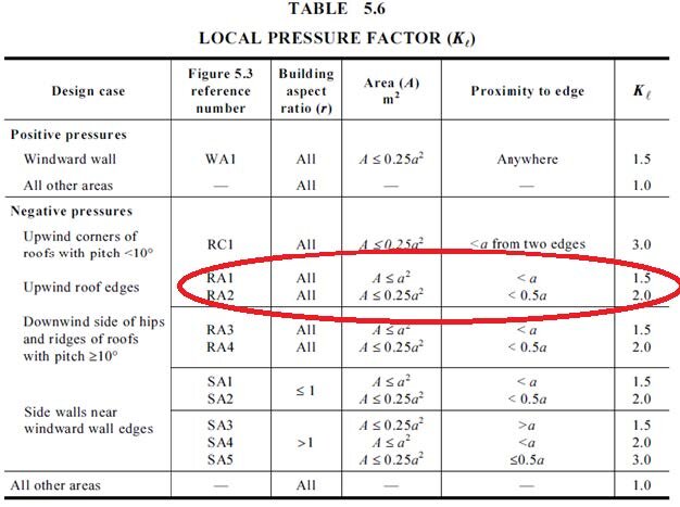
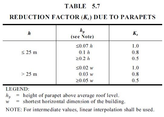
“For flat or near-flat roofs (slope less than 10°) with parapets, values of KL for areas RA1 and RA2 in the lee of the parapet may be modified by multiplying the values from Table 5.6 by the parapet reduction factor (Kr), given in Table 5.7.
This essentially means that only the intermediate and edge zones of a roof can be analysed.
Internal and corners zones are exempt from the parapet coefficient reductions.
Image 2 – Local pressure factors (Kl) - courtesy of AS / NZS 1170.2:2011
Image 3 – Reduction factor (Kr) due to parapets – courtesy of AS / NZS 1170.2:2011
The following information needs to be measured to calculate the shielding effect of a parapet wall on a roof structure:
Slope of the roof (in degrees).
Total height of the building (in metres).
Total height of the tallest parapet wall (in metres).
Total width of the building (in metres).
Total length of the building (in metres).
CASE STUDY
Take the example to a commercial building with the following specifications:
Roof slope of 3 degrees.
Building height (h) of 5 metres.
Building width (w) of 20 metres.
Building length (l) of 50 metres.
Parapet height (p) is 1 metre.
To determine the width of the intermediate and edge zones, calculate the each of the following values, and then using the smallest:
0.2 x w (0.2 x 20 = 4 metres)
0.2 x l (0.2 x 50 = 10 metres)
h (1.0 x 5 = 5 metres)
In summary the roof can be divided up into the following:
Internal zone > 4 metres from roof edge.
Intermediate zone 2 to 4 metres from roof edge.
Edge zone < 2 metres from roof edge.
Corner zone 4 metres (square area) from both roof edges.
The next step is to divide the height of the parapet (1 metre) by 2 giving a total of 0.5 metres.
This equates to the height of the parapet at the average roof level (hp).
Refer to Table 5.7, noting that the building is less than 25 metres tall.
Multiply the following:
≤ 0.07 x h (≤ 0.07 x 5) ≤ 0.35 metres
0.1 x h (0.1 x 5) 0.50 metres (this value correlates with hp, thus use the Kr value of 0.8)
≥ 0.2 x h (≥ 0.2 x 5) ≥ 1.00 metres
For any intermediate values, linear interpretation shall be used.
To conclude, the parapets ensure that the intermediate and edge zones are wind shielded by a factor of 0.8 or 80% compared to a building without a parapet wall.
This can potentially mean that less fixings / brackets and general PV framing can be used, saving time and money.
For Further information
For further information contact SunLock on 1300 655 554 or order@sunlock.com.au.


