Solar Mounting System | Sunlock — TechBulletin ***

Lilian

SunLock v3 Channel and Feet

INTRODUCTION

SunLock v3 channel is a lightweight and durable aluminium channel, suitable as a stand-alone frame or for use as an additional sub-frame to support SunLock solar PV frames. It is extruded from 6005-T5 aluminium for high strength and durability, and is available in 4.4m length and made-to-order lengths of 4.6m and 6.5m.

The taller design also allows the channel to safely route cables and connectors without the need for additional clips or cable ties.

SunLock channel feet provide a simple method of attaching the channel to the roof. The feet (extruded from 6005-T5 aluminium) are available in two types:

  • SLCF2 – to attach to a purlin via one 14 gauge roofing screw.

  • SLCF3 - to attach to a purlin via two 14 gauge roofing screws (when extra fixing capacity is required).

SLSCC3

SLSCC3

SLCF2

SLCF2

SLCF3

SLCF3

SLCN

SLCN

The v3 channel and feet can be used in conjunction with the standard SunLock channel joiners and channel lid. 

GUIDE TO USE

 The following guide illustrates how to install SunLock v3 channel and feet in a typical commercial application: 

1. Identify where the PV array, railing should be located on the roof and identify which existing fixings need to be utilised. 

2. Remove existing roofing screws. Place slotted channel feet (SLCF2) directly over holes in the roof sheeting ensuring an EPDM washer separates both items. Secure with suitable roofing screw. 

3. Repeat Step 2 and make sure that all adjacent channel feet are parallel to each other. 

Channel feet (SLCF2) fastened to roof sheet (w/ EPDM washers / roof screws)

Channel feet (SLCF2) fastened to roof sheet (w/ EPDM washers / roof screws)

4. Place lengths of channel into cavity of the feet. Make sure that the cap screws are loosened enough to ensure channel can be inserted easily. Once aligned properly, securely tighten cap screws.

SunLock channel (SLSCC3) fastened to feet

SunLock channel (SLSCC3) fastened to feet

5. To another layer of channel is to be built on top, place channel foot (SLCF2) on top of the channel, ensuring the nut fully engages with the internal lips of the channel. Make sure the channel foot is aligned perpendicular to the lower feet. Slide into desired position and tighten cap screws. 

Channel foot(SLCF2) mount on top of SunLock Channel with Channel Nut (SLCN)

Channel foot(SLCF2) mount on top of SunLock Channel with Channel Nut (SLCN)

6. Place the upper lengths of channel into cavity of the feet. Make sure that the cap screws are loosened enough to ensure the channel can be easily inserted. Once aligned properly, securely tighten cap screws. 

SunLock channel (SLSCC3) fastened to feet

SunLock channel (SLSCC3) fastened to feet

7. Once the final layer of channel has been installed, fixed tilt brackets can be mounted directly on top with M8 stainless steel cap screws. PV panels can be mounted directly onto the channel if required. 

ALWAYS USE ENOUGH FIXING POINTS

The primary aim of AS/NZ1170.2:2021 is to prevent injury to people and damage to infrastructure from PV arrays detaching from roofs in high winds and then hitting something. The risk of this occurring is negated by using a sufficient number of fixing points to attach the SunLock frame to the roof frame.

SunLock channel is an extra layer of framing between SunLock and the roof. It can spread the load, but does not mean that fewer fixing points can be used.

Step 1: Calculate the total number of fixing points you need

Use the SunLock general engineering report, for the wind region and topography of the site. Use the fixing spacing from the table to calculate the total number of fixings for the whole frame. This could be, for example, 36 fixing points.

Step 2: Determine how many fixing points can be attached to each channel

For example, if a section of channel crosses 4 purlins between the gutter and the ridge cap, it can use 4 fixing points.

Step 3: Calculate how many sections of channels are needed

Divide the total number of fixing points for the job, by the number of fixing points per channel. For example, 36 ÷ 4 = 9 channels are required. The channels can be roughly evenly spaced, based on the complexities of the site.

INSTALLATION EXAMPLE

In this case, two rows of 5 PV modules must be fixed to the roof. The problem is that the purlins are spaced at 2500 mm, which is too widely spaced to suit the SunLock rails. The site is in wind region A and the roof is pitched at 20 degrees, so we use drawing S5 from the SunLock installation manual v4. The “normal’ fixing spacing can be determined by assuming a purlin spacing of 1200 mm, which produces a fixing spacing of 1100 mm in the internal zone and 555 mm in the edge zone.

The PV modules are ~1 m wide so the row of 5 modules is ~ 5 m long. In this example, the rows of fixings near the gutter and near the ridge cap are in the roof edge zone, so the fixing spacing has to be 555 mm. This results in 9 fixing points per rail = 18 fixing points per row.

SunLock Channels are laid North-South between the gutter and the ridge cap, and can attach to the roof at 4 points each (2 points per row). The number of channels required is 18 ÷ 2 = 9. The channels are spaced as evenly as possible.

Fixing points.png

For Further information

For further information contact SunLock on 1300 655 554 or order@sunlock.com.au.

Concealed Fixings

INTRODUCTION

Some roofs are attached to the roof frame using concealed fixings. Examples include Klip-Lok, KingKlip or Speed Deck. These roofing systems do not have any penetrations (piercings or holes) in the roof sheet and when standing on the roof there are no screw heads to be seen. The roof sheet is clipped onto concealed fixings which in turn are fixed to the battens with standard screws. Thus, the total fixing capacity is defined by the total number (and type) of screws used to hold the concealed fixings to the battens. 

CLAMPS

Clamps are available that are designed to attach to the roof sheet without piercing it. SunLock have our own, as they can supply load capacity ratings based on test data.

Kliplok 406 and 700

Trapezoidal Bracket

Longline

Use the correct clamp 

Every roof sheet has a different geometry. The make and model of roof sheet must be identified prior to sourcing the correct clamps. If the wrong clamp is used it either won’t fit or will crush or tear the roof sheet as it is tightened up. SunLock however has a configurable clamp that fit most of the sizes, so you don’t have to worry about getting the wrong clamp.

Contact SunLock for advice on selecting the correct clamp for your roof sheet. 

Use clamps as a 1:1 replacement for screws 

When installing a SunLock flush-mount or tilt frame, use the SunLock installation manual to work out how many roof screws are required. Then, use the same number of clamps – i.e. one clamp replaces one roof screw. 

Although some manufacturers can provide test results showing that clamps are stronger than a roof screw, these laboratory tests are conducted using ideal conditions such a new screw perfectly installed in a new timber purlin. In real life the condition of the battens and screws are not as good and therefore the clamps must be de-rated to the value shown in the SunLock manual for one roof screw fixing. 

Locate the clamps directly over the concealed fixings 

Concealed fixings can be located by either looking for a slight bump in the roof sheet or by gently pressing a boot down on the roof sheet whilst sliding the boot back and forth. The roof sheet has some give while the concealed fixing is stiff. 

Never install a clamp in between two battens / purlins. The roof sheet is not a structural component and is not strong enough to transfer the extra load of the solar PV array sideways to the next batten. The roof sheet is only strong enough to withstand its own wind loads. 

Join several clamps with a rail / channel 

One clamp by itself can rock or move slightly under fluctuating wind loads. By bolting clamps to a rail or channel this rocking motion is eliminated. 

 These clamps attach to the crest of the roof (directly over the concealed fixing) and therefore transfer the wind loads directly into the concealed fixing, the screw and on to the batten. 

TIPS

SunLock channel feet (SLCF2) are quick and easy to bolt to the clamps and attach to channel v2 (SLSCC3). 

Solar panel roof rack mounting kit
Commercial Solar panel fixing rails

For Further information

For further information contact SunLock on 1300 655 554 or order@sunlock.com.au.

Edge Zones

INTRODUCTION

The SunLock General Engineering certificate helps installers to know how many roofs screws are required to securely hold the solar PV frame to the roof frame. This depends (in part) on the wind speed, which is higher in the edge zones of the roof. The image below shows how low pressure zones develop on the leading edge of each roof. As the wind could come from any direction, the standard defines edge zones on all edges of the roof.

The wind region map below also shows the structures should meet the standard required for installation for the region where it is installed according to AS/NZ1170.2:2021 standards.

TechBulletin_Edge-Zones_.jpg

GUIDE TO USE

 Measure the overall breath ‘B’, depth ‘D’, and height ‘H’ of the house. 

TechBulletin_Edge-Zones.jpg

For example, ‘D’ is 10 metres, ‘B’ is 13 metres, and ‘H’ is 4 metres. The edge zones comprise the intermediate zone and the edge zone, which are in total ‘A’ wide. ‘A’ is the minimum value of either: 

  • 0.2 * B, 

  • 0.2 * D, or 

In this case, ‘A’ is 0.2 x 8 = 2 metres wide. In most cases, the internal zone on the roof will be very small, and it is almost impossible to install a solar PV system within it. The image below shows the internal zones in yellow. 

TechBulletin_Edge-Zone.jpg

The edge zone and the intermediate zone are each ‘A/2’ wide. As a rough guide, use the fixing spacings for the “intermediate zone” shown in the table in the installation manual to work out how many you need. Then, add extra fixings if the row extends right into the edge zone. 

TechBulletin_Edge-Zones_1.0.jpg

For Further information

For further information contact SunLock on 1300 655 554 or order@sunlock.com.au.

Thread Locking

Introduction

SunLock uses stainless steel machine screws (also called bolts) in a variety of assemblies. These are usually threaded into aluminium. This technical bulletin describes how the screws are prevented from loosening (i.e. how the thread is locked).

PREVENTING A BOLT FROM LOOSENING

SunLock uses two methods to prevent bolts from loosening.

  • Correct fastener torque (12 - 14 N·m)

  • Growth of an aluminium oxide layer

Correct torque

The most effective and reliable method of preventing any nut or bolt from loosening is to tighten the thing properly to start with. Carroll Smith’s nuts, bolts, fasteners and plumbing handbook, 1990, page 116.

For SunLock, please tighten bolts to 12 - 14 N·m, as per the SunLock technical bulletin on fastener torque.

Growth of an aluminium oxide layer

SunLock is fabricated from mill finish aluminium (non-anodised). As a bolt is tightened, the aluminium oxide layer is scraped away by the incoming stainless steel thread. After installation, the oxide layer reforms, bonding slightly to the stainless bolt and “locking” it in place. This has a similar effect to thread-locking fluid.

NOTE ON LOCK WASHERS

Similarly, SunLock does not use helical spring washers, as the spring force created by the washer is far less than the axial tension in the bolt. They effectively act as a flat washer.

REFERENCE

Barrett (1990) Fastener Design Manual, NASA

Smith (1990) Carroll Smith’s nuts, bolts, fasteners and plumbing handbook, Motorbooks International.

Tomotsugu (2008) Bolted joint engineering: Fundamentals and Applications, Beuth.

For Further information

For further information contact SunLock on 1300 655 554 or order@sunlock.com.au.

Is your rooftop suitable for solar?

INTRODUCTION

A “solar ready roof” will simplify the later installation of a solar PV array. This technical bulletin is intended to assist architects, building designers and structural engineers to design solar ready roofs.

ISSUES TO CONSIDER

Roof coverage

Buildings can last more than 100 years. As market for solar PV matures, building owners may wish to cover the entire roof with a solar PV array. Such installations are already common in Europe and the USA. Therefore, building designers should allow for this scenario.

Roof pitch

The ideal roof pitch is 10° to 30°, as it is cheaper and easier to install a solar PV array flush (or parallel to) the roof than to use a tilt frame. Note that a solar PV array should be inclined at least 10° above horizontal to allow rain to clean the modules and to prevent the buildup of dirt or deposits.

Static load

A solar PV array will increase the static load on the roof by 10 – 15 kg/m2. Typically, this won’t impact the design of the building frame as the frame will already have capacity to withstand a live load of 25 kg/m2.

However, some large cost-optimised commercial buildings may be limited by a combination of static load and wind down force. In these cases the purlins and rafters will need to be upsized.

Wind load

A solar PV array is subject to wind actions (uplift or down force) defined by AS/NZS1170.2. Different zones of the roof are exposed to different loads. Furthermore, tilted PV arrays are subject to larger wind actions than flush mounted arrays. Either SunLock or our partner Gamcop structural engineers can assist with these calculations.

Typically, uplift governs the design of the solar PV frame and its method of attachment to the building frame.

Fixing method

The simplest, fastest and lowest total cost method is to fix the solar PV frame to the building frame using standard roofing screws. This requires the building to use standard sheet metal roof cladding.

Membrane roofs are not recommended as they are very difficult to fix through.

Durability of roof cladding

Sheet metal roof cladding with 0.48 mm BMT will be more durable than the 0.42 mm BMT commonly used on domestic residences. Commercial solar PV installations require more time and traffic on the roof than domestic installations - the thicker cladding offers a lower lifetime cost.

Parapets

Note that parapets can reduce the wind load on nearby solar PV arrays but can also increase shading.

Roof access

Installation and maintenance personnel need to be able to access the roof, move safely about on the roof and access the solar PV array from all sides. On domestic residences it is useful to maintain a 1 m gap between the roof edge and the array. On commercial buildings a 4 m gap is typical. Commercial roofs should be provided with safe access points and harness attachments points.

Certification

SunLock provides installation manuals for download at www.sunlock.com.au. Contact SunLock for site specific advice or certification if required.

Summary & Recommendation

Designing a solar ready roof adds little to the capital cost of a building but can be critical to allowing the building roof to be partially or fully covered by solar PV.

Residential

SunLock recommends using standard sheet metal roof cladding pitched at 10° to 30° and fixed using standard roofing screws.

If the building will use light weight engineered trusses, ask the truss supplier to design (and warrant) their product with sufficient capacity to allow the entire roof to be covered with a solar PV array.

Commercial

SunLock recommends using 0.48 BMT sheet metal roof cladding pitched at 10° and fixed using standard roofing screws. Purlins should have a maximum spacing of 1800 mm.

If the building will use a light weight cost optimised frame, ask the structural engineer to design the building frame with sufficient capacity to allow the entire roof to be covered with a solar PV array. This will most likely require minor changes to the frame such as upsizing purlins and some rafters.

For Further information

For further information contact SunLock on 1300 655 554 or order@sunlock.com.au.

Solar Panel Installing Inclination

INTRODUCTION

When not mounted flush on a roof, PV modules should be inclined at the optimum angle to maximize the annual energy output of the system. For grid connected systems, this angle is 10 degrees lower (flatter) than the latitude of the site.

TechBulletin_Inclination_1.1.jpg

Example: Sydney’s latitude is 34°. The optimum inclination is 10° lower, or 24°

GUIDE TO USE

The minimum inclination angle should be 10° to take allow rainfall to clean the modules. As a guide, the following table summaries the optimal inclination for Australian capital cities.

Solar Panel Installing Inclination.png

STAND ALONE SYSTEMS

Stand alone systems seek to maximize the energy generated in the winter months. These systems should be more steeply inclined, at latitude plus 10 degrees. However, to maximise energy generation In summer, advice tilt angle should be latitude minus 10 degree.

REFERENCE

This general rule is derived from the “Your Home Technical Manual”:

http://www.yourhome.gov.au/technical/fs67.html

Another good reference literature

https://www.solarpaneltilt.com

COMPLIANCE WITH CEC GUIDELINES

This advice complies with CEC guidelines, as stated in the CEC’s System Installation Guidelines for

Accredited Installers and Supervisors, Issue 6, September 2010.

For best year-round performance, a fixed PV array should be mounted facing true north (± 10°) at an inclination equal to the latitude (± 10°) angle or at an angle that will produce the best annual average performance taking into consideration: seasonal cloud patterns, local shading and environmental factors.

For Further information

For further information contact SunLock on 1300 655 554 or order@sunlock.com.au.

Parapets

INTRODUCTION

A parapet is a wall-like structure surrounding the edge of a roof. Essentially it is a wall or railing at a height of approximately one metre. This can be a safety feature in that it is designed to stop falls from the edge of the roof but it can also be a defensive, constructional or stylistic feature.

Parapets can be used to give a roof the appearance of a flat roof.

As a parapet shields or breaks the wind flow over the leading edges of a typical roof, it can be used to optimise the framing design in areas of the roof that traditionally experiences higher loadings.

 
Image 1 – Typical parapet wall in background - courtesy of NextDC

Image 1 – Typical parapet wall in background - courtesy of NextDC


STANDARDS

The AS / NZS 1170.2-2011 standard on wind actions incorporates parapets into building design.

Information on the impact of parapets on wind actions can be found on p. 37- 39 of the standard.

UNDERSTANDING EFFECT OF PARAPETS ON ROOF WIND PRESSURES

On p.37 of the standards, it states:

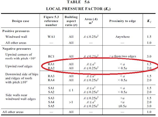
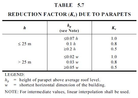
“For flat or near-flat roofs (slope less than 10°) with parapets, values of KL for areas RA1 and RA2 in the lee of the parapet may be modified by multiplying the values from Table 5.6 by the parapet reduction factor (Kr), given in Table 5.7.

This essentially means that only the intermediate and edge zones of a roof can be analysed.

Internal and corners zones are exempt from the parapet coefficient reductions.

 
Image 2 – Local pressure factors (Kl) - courtesy of AS / NZS 1170.2:2011

Image 2 – Local pressure factors (Kl) - courtesy of AS / NZS 1170.2:2011


Image 3 – Reduction factor (Kr) due to parapets – courtesy of AS / NZS 1170.2:2011

Image 3 – Reduction factor (Kr) due to parapets – courtesy of AS / NZS 1170.2:2011


The following information needs to be measured to calculate the shielding effect of a parapet wall on a roof structure:

  • Slope of the roof (in degrees).

  • Total height of the building (in metres).

  • Total height of the tallest parapet wall (in metres).

  • Total width of the building (in metres).

  • Total length of the building (in metres).

CASE STUDY

Take the example to a commercial building with the following specifications:

  • Roof slope of 3 degrees.

  • Building height (h) of 5 metres.

  • Building width (w) of 20 metres.

  • Building length (l) of 50 metres.

  • Parapet height (p) is 1 metre.

To determine the width of the intermediate and edge zones, calculate the each of the following values, and then using the smallest:

  • 0.2 x w (0.2 x 20 = 4 metres)

  • 0.2 x l (0.2 x 50 = 10 metres)

  • h (1.0 x 5 = 5 metres)

In summary the roof can be divided up into the following:

  • Internal zone > 4 metres from roof edge.

  • Intermediate zone 2 to 4 metres from roof edge.

  • Edge zone < 2 metres from roof edge.

  • Corner zone 4 metres (square area) from both roof edges.

TechBulletin_Parapets_1.0.jpg

The next step is to divide the height of the parapet (1 metre) by 2 giving a total of 0.5 metres.

This equates to the height of the parapet at the average roof level (hp).

Refer to Table 5.7, noting that the building is less than 25 metres tall.

Multiply the following:

  • ≤ 0.07 x h (≤ 0.07 x 5) ≤ 0.35 metres

  • 0.1 x h (0.1 x 5) 0.50 metres (this value correlates with hp, thus use the Kr value of 0.8)

  • ≥ 0.2 x h (≥ 0.2 x 5) ≥ 1.00 metres

For any intermediate values, linear interpretation shall be used.

To conclude, the parapets ensure that the intermediate and edge zones are wind shielded by a factor of 0.8 or 80% compared to a building without a parapet wall.

This can potentially mean that less fixings / brackets and general PV framing can be used, saving time and money.

For Further information

For further information contact SunLock on 1300 655 554 or order@sunlock.com.au.

Row Spacing between Commercial Tilt Frames

INTRODUCTION

Rows should have sufficient spacing to prevent shading and maximize solar yield. The required row spacing depends on the following (for north facing rows):

- Geographic location (in particular, the latitude)

- Vertical distance between the top of one row and the base of the next

- How many hours of the day the rows must remain unshaded

DETERMINING THE CORRECT SPACING

Measure vertical difference

Measure the vertical difference in height between the lowest part of one row and the highest part of the next row. This takes into account the slope of the roof or ground.

Multiply this height by a factor

To determine the gap between the panels, multiply the height by a factor. This factor accounts for the location of the sun (altitude and azimuth) on the winter solstice. At minimum (and in accordance with CEC guidelines) the panels should not be shaded between the hours of 10 am to 2 pm.

To further minimize shading and maximize yield, it is recommended to avoid shading from 9 am to 3pm. If a lot of space is available then an even better solution is to avoid shading from sunrise (+ one hour) to sunset (- one hour), as shown in the following table:

 
Row Spacing.png
 

Add this to the row width

To get the row spacing add the row width (width of the panels) to the row gap (just calculated).

WORK EXAMPLE

Measure height

Solar modules are installed on 15° commercial roof brackets on a north facing roof with a pitch of 3°. The difference in vertical height is ~ 260mm. For 10° commercial roof brackets, use vertical height of ~ 160mm.

Multiply this height by a factor

The solar modules are installed in Perth and should be unshaded from 9 am to 3 pm on the winter solstice. Use the SunLock factor of 2.3. Therefore, the row gap is 260 mm x 2.3 = 598 mm.

Add this to the row width

The solar module has a width of ~ 956 mm. Therefore, the total row spacing is 956 mm + 598 mm = 1554 mm.

LOOK UP TABLES

Commercial roof brackets on a north facing roof with a 3° pitch:

Note: minimum row spacing is 1200 mm.

Note: minimum row spacing is 1200 mm.

Commercial roof brackets on a south facing roof with a 3° pitch:

Note: minimum row spacing is 1200 mm.

Note: minimum row spacing is 1200 mm.

For Further information

For further information contact SunLock on 1300 655 554 or order@sunlock.com.au.